Structure of bitcode file
An LLVM bitcode file is organized as a sequence of blocks and data records as shown in Figure 2.1. A ile header is at the beginning of the bitcode file. The first two bytes of the bitcode file are `BC' and the second two bytes contains the application specific magic number.
Figure 2.1
The bitcode file is processed sequentially as a stream of bits by a bitcode parser. Such stream of bits is referred as a bitstream or just a stream in this document.
Blocks in a bitsstream can have the nested blocks called sub-blocks or the data records. Both the blocks and the records start with an abbreviation ID also referred as record ID in this document. It can either be a builtin ID with a special meaning or the one defined in stream itself. There are four builtin abbreviation IDs as shown in Table 2.1.
| ID | Type | Description |
|---|---|---|
| 0 | END_SUBBLOCK | Mark the end of the current block |
| 1 | ENTER_SUBBLOCK | Marks the start of a new block |
| 2 | DEFINE_ABBREV | Defines a new abbreviation |
| 3 | UNABBREV_RECORD | Defines an unabbreviated record |
Table 2.1
Record ID need to be defined before its usage. Stream defined IDs use the DEFINE_ABBREV records for their definition. This will be explained in Section \ref{sect:defineAbbrev}.
Listing 2.1 shows a simple C code example that will be used for explaining the organisation of the bitcode file.
int main(){
    int a = 2;
    a = a + 5;
    return a;
}
Listing 2.1
An LLVM IR for the sample.c file is generated using the following command.
clang -emit-llvm -c sample.c -o sample.bc
The llvm-bcanalyzer tool can be used to inspect a bitstream which is not human readable otherwise. The following command can help inspecting the sample.bc file generated earlier.
llvm-bcanalyzer -dump sample.bc
Listing 2.2 shows a high level block structure from the output of llvm-bcanalyzer for sample.bc.
<MODULE_BLOCK NumWords=222 BlockCodeSize=>
  ...
   <TYPE_BLOCK_ID...>
  ...
  </TYPE_BLOCK_ID>
  <TRIPLE .../>
  <DATALAYOUT .../>
  ...
  <FUNCTION_BLOCK NumWords=17 BlockCodeSize=4>
    <DECLAREBLOCKS op0=1/>
    <CONSTANTS_BLOCK NumWords=2 BlockCodeSize=4>
      ...
    </CONSTANTS_BLOCK>
    <INST_ALLOCA .../>
    ...
    <INST_RET abbrevid=9 op0=1/>
    ...
  </FUNCTION_BLOCK>
</MODULE\_BLOCK>
Listing 2.2
In the Listing 2.2 a sequence of blocks in the bitcode file could clearly be seen. Here the MODULE_BLOCK wraps all the other blocks. It contains a record TRIPLE for the target triple specification string and a record DATALAYOUT for the datalayout specification. FUNCTION_BLOCK is an example of the nested blocks having a sub-block of type CONSTANTS_BLOCK for listing the constants and has records for representing the instructions for a code shown in the Listing 2.1.
Figure 2.2 shows a logical structure of a bitcode file as a combination of blocks and records. Listing 2.2 shows the content of a bitcode file in XML like format. However, physically a bitcode file is stored simply as a sequence of varied size records as shown in Figure 2.1.
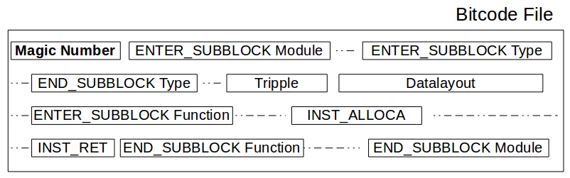
Figure 2.2
Figure 2.2 represents the sample.bc file. Interpretation of the records in a bitcode file gives it the logical structure of nested block and records as shown in the above figure. This interpretation is performed by the bitcode parser.